Step 1. - Reset 3D Studio Max
Step 2. - Go to the Front View
Step 3. - Go to the Create Panel 
Step 4a. - Open your favorite image editor (PhotoShop / PaintShop Pro etc.) and make a track like image that can be repeated over and over. This will be the bump map for the track of the tire. Make it something like this one: (or even better: save this image as tire-track.JPG or something, saves a lot of time :p )
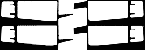
Step 4b. - Make a new picture, make it square and draw the side of the tire: preferably some marks like 'Pirelli P-Zero' or something like that. Take the one below if you want to move on. If you make a real tire for an already built car, then make your own texs that fit with the car, but for now I would advise you to just take the ones that are placed here. I am not fond of the one below, but hey: I also found it somewhere and am too lazy to make a new one...

Image © 2001 Dominick Clift
Step 5. - Now go close the painting program and go back to 3D Max.
Step 6. - Select the tube again and set Height Segments to 6, Cap Segments to 2 and Sides to 30.
Step 7. - Right Click the tube in a viewport and select: convert to... editable mesh. We want this because we'll first make the outer tire a bit more round to give it that little extra realism.
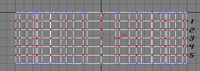
Step 8. - Now go to the Vertex Sub-Object level and select the middle 5 rows in the top viewport:
Step 9. - Go back to the front viewport, and select the Circular Selection Region 
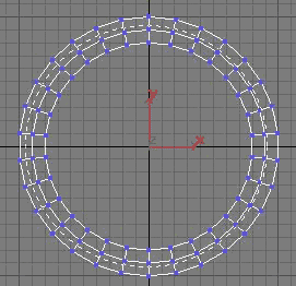
Step 10. - Select the Non-Uniform Scaling mode 

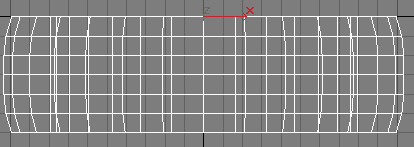
Step 11. - Apply a MeshSmooth modifer to the tube, and set iterations to 1. Now we have a good tire, only where is the track? We have to add it! Yes! Indeed! :)
Step 12. - Go back to the Editable Mesh (= out of Meshsmooth) and go to the Face Sub-Object Level. Try to select the outer side of the tire, where the track is: the same method can be used here as we did before, only then in the Vertex Sub-Object Level. Use the circular selection method again and hold Alt to deselect the faces inside the tire.
Step 13. - With these faces selected, go to the Material Editor and in slot one set the color to: rgb(45, 45, 45), Specular Level to 75 and Shininess to 20. In the Maps roll-out, click on the BumpMap-button and select bitmap from the pop-up. Choose your tire track image. Now that you have done that, go back to the main Material (click the roll-out menu with Map #1 in it and select 1 - Default. You see that the BumpMap is your track now and a little v before Bump. That means it is active. Set the bump amount to 300.
Step 14. - Assign the material to the selection and click the 'Show Map in viewport' button (the blue-tiled-square). When you go out of the Face Sub-Object mode, and try to test-render it, it sais: 'The following objects require..yadayadayada'. What it means is that you need to apply an UVW-map modifier to your tube. Do that and select Mapping: Box. Click 'Fit' and try to render the perspective. You'll get something like this (Left Image):


Step 15. - As you can see: the mapping isn't too good, but is starts to look like something. You probably have guessed already that the map (the track) should be tiled and rotated. So that's what we'll do. Go to the Material Editor and click the Bump Map button. Now set the V-tiling to 10 and the W-rotation to 90 degrees. AAAH! Now that's cool! Look at that. Let's make a test render (Middle image)! Only those edges? Yes I know. Try this: make the size of the UVW-Map box 100x100x60 instead of 200x200x60 and reduce the V-tiling of the BumpMap from 10 to 5. After doing that and rendering you have the Right Image.
Step 16. - Now for the side of the tires: again go to the Face Sub Object mode (you might as wel throw the MeshSmooth away as we do not need it really) and select the side faces of the tire. If you do not know how then try this: in the Face Sub-Object mode press Ctrl+a (select all) and then in the top viewport deselect all the middle faces. With these faces selected go to the material editor and go to slot 2. In the diffuse button in the Maps rollout select Bitmap and choose your 'Pirelli side' that you made, or saved from this tutorial. Also here click 'View Map in viewport'. Hmmm... strange? No, of course not. It does not fit at all, because we made the UVW-map box twice to small! Remember? So, we'll set the U and the V-tiling of the side to 0,5 (= twice as large as normal). Adjust the tiling until it fits nicely. I had to make them 0.44. A test render should look something like this:


Step 17. - As you can see: the two images (the side and the track images) do not match at all. They have a different pattern, different colors etc etc. When you make a real tire, then make your own texs with the same colors etc, it will make it even better. Apply a MeshSmooth modifier again (if you threw the other one away) and set iterations to 1. Render and LO and BEHOLD! :) Nice, but hide the Tire for now, because we'll start with the alloys now.
Step 18. - Make a new tube, Radius1 = 85, Radius2 = 76, Height = 56, Height Segments = 5, Cap Segments = 2, Sides = 25. Convert it to an editable mesh. What we'll do now is 'densify' the sides of the tube so that it will remain a bit squarish after we apply a MeshSmooth modifier. You'll see what I mean later. First go to the Vertex sub-object level and in the top view select row 1 and (remember the image above? Only now with four rows, not counting the upper and lower row, like I did before). Anyways: select Non-Uniform scale and restrict to Y (F6). Scale them down to 30%, do the same for the lower two rows (3 and 4). Then move the upper scaled rows towards the top and the lower row downwards. You can see what I mean here:
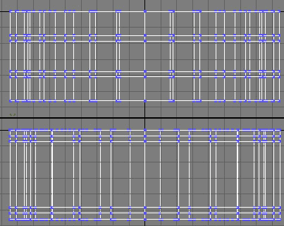
Step 19. - Again make a new tube: Radius1 = 76, Radius2 = 72 and the rest is the same as the other one. Do exact the same thing as you did with the other tube: 'densify'. After that: select both tubes (not the tire, naturally) and apply a MeshSmooth, iterations = 1. Unhide the tire.
Step 20. - Now we'll make a material for the alloy parts. Go to the Material Editor and go to slot 3. Set Diffuse Color to: rgb(195, 195, 195), Specular Level = 100. In the Maps rollout click the reflection button and select bitmap. Pick a blueish sky or something like that, it isn't really important but it gives a nice touch. Go back to the main material and set the reflection ammount to 25. Apply the map to the two tubes.
Step 21. - Now comes a very logic step, you might already have done it, but I have to do it (show you what to do if you didn't), because else you'll get some weird wheels! Select the tire and right click the move button. Set Absolute World to (0,0,0). The outer alloy tube: (0,-2.0, 0), and the inner alloy tube: (0,-5.0, 0). Render and hopefully you'll see this:

Step 22. - Now for the real alloy: make a cilinder, Radius = 27.5, set Height Segments to 1 and Sides to 18. Convert to... editable mesh. Go to the Face Sub-Object: select the outer faces only this way: one selected, one not, one selected, one not etc etc:
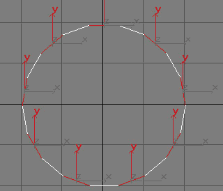
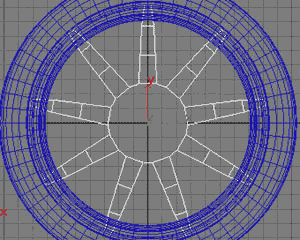
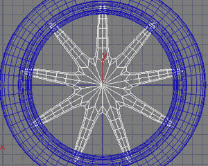
Step 23. - Make Bevel (in the editable mesh roll-out!) 1.5. Then Extrude 20, Bevel -1, Extrude 20, Bevel -1, Extrude 15, Bevel -2. Apply the same material to this object , as you did with the outer tubes of the alloy wheel and you should have something like this (Image Left) and with a MeshSmooth (iterarions = 1, Image Right):

Step 24. - To wrap this up: make two omni lights: one with multiplier is 1.0 and one with 0.5. And click 'Cast Shadows' with the one wit mp = 1.0, NOT with the one with mp = 0.5! The omni with the low mp is to show everynody more of the tire: light never comes from one side alone: to take this in extremis you could use a MaxSxript or plugin and create GI (global illumination) which gives the nicest effect: the ultimate realism. Anyway, place the omni's something like this:
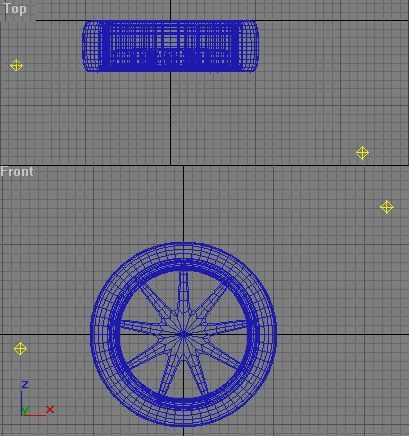
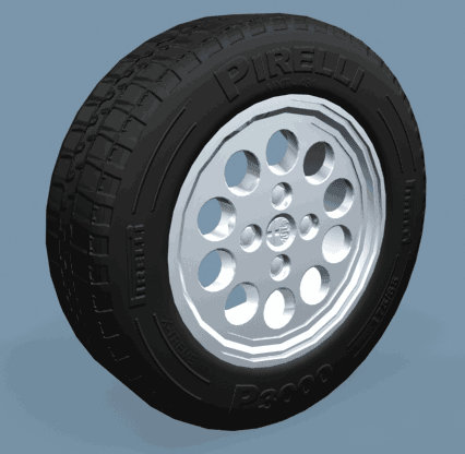
Step 25. - Make a plane 1000000x1000000, add a Matte Shadow map. This is a map that get's the same color as the environment, but DOES recieve shadows. Go to the Material Editor, go to a new material, click the Standard button and select Matte/Shadow from the pop-up. In the options that you'll get click recieve shadows and set Shadow Brightness to 0.5. Make some movement in the perspective view so that you get a nice camera angle and RENDER (Shift + q, or Shift + r for a pop-up of the render menu)!

And with about the same technique, for my model of an Alfa Romeo 33.
 Subscribe
0 comments:
Post a Comment